Understanding Ceramic Injection Molding for High-Precision Components
Can a single manufacturing route deliver metal-like tolerances, complex geometry, and heat-resistant material in one go?
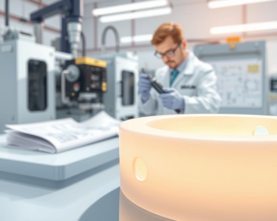
Here is a compact guide to a scalable manufacturing route that makes complex, high-accuracy ceramic components achievable: AMT. This method mixes fine powder with a binder to create feedstock. The feedstock is subsequently injection molded, debound, and sintered to reach near-theoretical density.
The main advantages include design freedom, repeatability, tight tolerances, and surface quality comparable to metal processes. This route is a strong fit when CNC or tape casting cannot efficiently produce small, highly detailed parts.
Expect dimensional change from shrinkage during sintering; early design-for-process thinking cuts rework and cost. This manufacturing route supports mid-to-high production volumes where tooling cost and cycle time are justified by part counts.
Use cases include aerospace, automotive, medical, electronic, and industrial parts that must resist wear, high temperature, or corrosive conditions. This article walks the step-by-step journey from materials selection through QA and highlights simulation and metrology tools to secure reliable outcomes.
Ceramic Injection Molding: What It Is and Why It Matters Today
The injection molding process for fine-powder components uses a thermoplastic or wax-based binder blended with powder to create a flowable feedstock. This feedstock is injected into complex cavities to form green parts whose features would be hard to realize via slip casting, dry pressing, or isostatic pressing.
How It Differs from Traditional Ceramic Forming
In contrast to slurry-based or powder-compaction methods, this route can form internal channels, undercuts, and thin walls in small-to-medium parts. Production throughput is generally higher, with reduced variability compared to many manual processes.
Where It Fits into Modern Manufacturing Workflows
A typical process flow is: design for shrinkage → build tooling → perform molding → carry out debinding → run sintering → apply finishing. Cycle times often range from seconds to a few minutes per shot. The economic sweet spot lies in mid-to-high volumes where tooling cost is amortized effectively.
“Design validation through DOE trials and pilot runs reduces risk before full production.”
| Method | Geometry Complexity | Production Throughput | Labor |
|---|---|---|---|
| Feedstock-based route | High — supports undercuts and internal channels | High throughput | Low (automatable) |
| Slip casting | Moderate complexity | Low | High labor input |
| Isostatic/dry pressing | Simple to moderate geometry | Moderate | Moderate labor requirement |
After sintering, lapping or laser-based features can be applied to refine tolerances. The route aligns well with SPC and PPAP systems, improving traceability and process control. Today, the main advantages are higher efficiency, reduced scrap, and the ability to realize designs that would otherwise be too expensive.
Ceramic Injection Molding: Core Principles of the Process
Here we break down the stepwise route that transforms fine powder and binder into a stable part suitable for sintering.
From powder and binder to a finished component
First, choose powder that offers the correct particle size distribution and surface area. These traits control packing density, viscosity, and the final microstructure.
- Blend powder with a tailored binder system and compound into feedstock with target solids loading (typically 55–65 vol%).
- Use injection to form a green part; pay attention to gate placement to avoid weld lines and uneven packing.
- Debind to yield a fragile brown part and then sinter it to near-theoretical density.
Binder systems must flow for good filling, hold shape during handling, and exit cleanly during debinding to prevent blisters or cracks.
The rheology of the feedstock—how viscosity changes with temperature and shear—determines filling, knit-line formation, and surface finish. CIM machine geometry and screw/barrel design protect feedstock homogeneity and prevent degradation.
“Keep the processing window tight — even minor changes in temperature or pressure can trigger short shots, voids, or bad surfaces.”
Compared with MIM, this route uses higher sintering temperatures and different atmospheres to match ceramic chemistry and densification needs.
Preparing Materials and Feedstock for High-Precision Ceramic Components
Choosing appropriate powders and binders lays the foundation for predictable, high-precision parts.
Choosing Powders and Key Specifications
Alumina excels where wear resistance and electrical insulation matter for https://amt-mat.com/precision-manufacturing-for-lidar-components-and-co-packaged-optics/. Zirconia provides improved fracture toughness in components that experience shocks. Silicon carbide works well where parts face high temperatures and abrasive conditions.
Maintain tight control over particle size, shape, and purity. Fine, spherical powder improves packing and surface finish. Irregular particles may raise green strength while potentially making the final surface less smooth.
Binder systems and ratios
Frequently used binder systems consist of waxes and polyolefins (for example, polyethylene and polypropylene), with specialty polymers for complex shapes. Binder percent affects melt flow and debinding time.
Compounding and Rheology Control
Compound with a steady sequence: dry powder blending, gradual polymer addition, then controlled temperature and shear. Keep peak processing temperatures in check to avoid degrading the binder system.
Evaluate feedstock using capillary rheometers or torque rheometers to confirm viscosity windows for dependable filling and packing. Aim for solids loading that balances density and shrinkage — typically around 55–65 vol% for high-density parts.
Storage, Handling, and Drying Practices
Store powders in tightly sealed containers and operate with FIFO inventory control. Manage humidity for hygroscopic components and thoroughly dry pellets before molding to minimize voids and surface defects.
Use appropriate PPE and dust controls whenever working with fine powders and hot polymers. Early supplier collaboration on powder and binder choices speeds validation and lowers iteration risk.
How to Design Parts for the Injection Molding Process
Designing for this route starts with clear goals: meet tolerances and limit post-sinter work. Early CAD decisions govern shrinkage behavior, mechanical strength, and handling of fragile green parts.
Wall thickness, gates, and knit line management
Maintain uniform wall thickness and gradual transitions to minimize sink marks and warpage. Place gates so flow moves away from cosmetic or high-stress areas to avoid knit lines in critical zones.
Incorporate a shrink map and scale important features in the mold to reach final dimensions. Validate with flow simulation and a DFM review before tooling.
Draft, Radii, and Features for Debinding and Sintering
Use moderate draft angles and sufficient radii to simplify demolding and reduce local stress. Integrate vents, sacrificial channels, or setters to speed debinding and support fragile shapes.
Choose datums and inspection references that reflect how components are supported in sintering and QC. Allow minimal finishing stock for critical fits while avoiding excess that raises cost.
| Design Focus | Guideline | Resulting Benefit | Check Method |
|---|---|---|---|
| Section Thickness | Uniform sections with smooth transitions | Reduced warpage and more predictable shrinkage | Simulation / prototype |
| Gate placement | Place away from cosmetic or high-stress regions | Reduced knit lines | Flow-simulation review |
| Features for Debinding | Vents, channels, setters | Safer brown parts with fewer cracks | Design-for-manufacture review |
Tooling and Mold Design for Ceramic Injection Molding
A well-engineered toolset cuts scrap and enhances dimensional control over long production runs. Start by choosing tool materials and surface treatments that withstand abrasive feedstock and tight tolerances.
Tooling materials must withstand abrasion and repeated thermal cycling. Choose high-performance steels or nickel-based alloys, and apply wear-resistant coatings to extend tool life.
Balance cavity surface finish to support easy release yet preserve fine detail. Steer clear of https://amt-mat.com/medical-devices-assembly-process textures that capture binder and encourage sticking. Engineer venting to clear air and volatiles and prevent burn marks or short shots.
- Choose gate types (edge, submarine, hot tip) and runner layouts to promote balanced filling and reduce weld lines.
- Refine cooling circuits to hold cavity temperatures steady and reduce variation between cycles.
- Use robust ejection—stripper plates or air assist—to protect fragile green parts during demold.
- Employ interchangeable inserts so gates, vents, and critical features can be adjusted quickly.
- Account for tolerance stack-ups by adjusting cavity dimensions for expected shrinkage.
- Embed in-cavity pressure and temperature sensors to monitor the process and enable closed-loop control.
- Schedule maintenance intervals and abrasion inspections to keep performance consistent over long runs.
These steps improve dimensional control and cut down on downstream rework. They also promote scalable production with modern molding technology and protect tool investment.
Running the Injection Molding Stage Step by Step
A repeatable press cycle relies on stable temperature profiles, controlled pressure ramps, and consistent operator discipline. Start with a clear start-up checklist that protects feedstock and machine from thermal shock.
Machine setup: temperature, pressure, and injection speed
Adjust barrel and mold temperature profiles to stabilize viscosity and prevent binder breakdown. Dial in injection speed and pressure ramps to fill complex features while avoiding jetting and flow lines.
Filling, packing, and cooling for tight tolerances
Employ multi-stage packing profiles to compact green parts and minimize internal voids. Balance cooling duration to achieve adequate handling strength without sacrificing cycle efficiency. Use structured purging and changeover routines so different feedstocks do not cross-contaminate.
Protecting Green Parts During Demolding
Apply low-friction coatings and measured mold release where needed. Use controlled ejection and guarded fixtures to protect delicate features. Ensure operators are trained to detect early defects and pause the run when required.
| Control | Set Point | Key Benefit |
|---|---|---|
| Barrel / mold temp | Stable viscosity range | Fewer short shots; consistent surface |
| Injection pressure/speed profile | Programmed multi-stage | Complete fill; reduced weld lines |
| Packing/cooling strategy | Multi-stage; balanced time | Uniform density; dimensional stability |
Best Practices for Debinding in Ceramic Injection Molding
Successfully removing binder is a crucial step in transforming a fragile green part into a sinter-ready component.
Two primary debinding methods are widely used: solvent debinding and thermal debinding. In solvent debinding, the soluble portion of the binder is extracted initially. Thermal debinding then removes the remaining polymer by controlled pyrolysis.
Comparing Solvent and Thermal Debinding
Solvent debinding rapidly extracts soluble binder components, easing internal pressure for the next stage. Thermal debinding is slower but needed to remove hard-to-dissolve polymer. Choosing the right method depends on binder chemistry and part geometry.
Avoiding Defects During Debinding
The choice of fixtures and the orientation of the parts are critical. Support fragile areas and allow free escape paths for volatiles to prevent cracking and distortion.
Apply gentle heating ramps, staged holds, and controlled airflow to avoid pressure spikes that produce blisters. Parts with thick walls or blind cavities often need extended cycles or additional venting.
Choose recoverable solvents and maintain effective ventilation. Adhere to MSDS instructions and local environmental rules to protect personnel and stay compliant.
- Use test coupons and sacrificial parts to confirm full binder removal prior to sintering.
- Watch for odor, discoloration, or unexpected mass loss profiles—these indicate incomplete debinding.
- Troubleshoot skin formation, delamination, or slumping by reducing ramp rates, improving venting, or revising fixtures.
Debinding success ties back to molding and injection quality; voids or knit lines often become failure points during removal. Record debinding curves and mass-loss data to standardize the process and protect final part quality.
Sintering to Final Density and Performance
Controlled sintering is the step that transforms a fragile brown shape into a dense, service-ready part. The furnace cycle sets microstructure, porosity, and mechanical properties that determine long-term performance.
Controlling Temperature, Atmosphere, and Shrinkage
Apply a three-step profile: a slow heat-up to remove residual binder, a controlled ramp into densification, and a measured cool-down to prevent thermal shock.
Match the furnace atmosphere to the material: air for alumina-type oxides, inert or reducing gases for carbides and engineered blends. A suitable gas atmosphere maintains chemistry and color and reduces adverse grain-boundary reactions.
Use sacrificial coupons to track shrinkage and feed those results into cavity compensation. Design setters and supports to restrain warpage and allow uniform gas flow.
Reaching Target Strength, Corrosion, and Wear Resistance
Sintering adjusts grain size and porosity, which in turn drive flexural strength and fracture toughness. Target high density with controlled grain growth to hit strength objectives.
Tune material chemistry and soak schedules to maximize corrosion resistance and surface hardness for wear. Use post-sinter HIP when remaining porosity compromises fatigue or sealing behavior.
- Document recipes and use thermocouples or pyrometry to validate furnace performance.
- Control part orientation and spacing to ensure even temperature and atmosphere exposure.
- Watch for defects: slumping, exaggerated grain growth, and trapped porosity—slow ramps and better support often fix these.
| Key Parameter | Typical Target | Effect on Properties | Manufacturing Tip |
|---|---|---|---|
| Ramp Rate | About 1–5 °C/min in debinding, 5–20 °C/min in sintering | Reduces cracking; controls grain growth | Match ramp to binder chemistry and part mass |
| Soak Temperature and Time | Peak temperature defined by material; soak from minutes to hours | Density increase; porosity closure | Use test coupons to fine-tune soak |
| Atmosphere | Air, inert, or reducing gas matched to material | Preserves chemistry and prevents unwanted oxidation | Use flow meters and gas purity checks |
| Post-sinter processing | Hot isostatic pressing or annealing | Reduces porosity and enhances mechanical strength | Use for parts that require maximum performance margins |
“Stable sintering recipes and validated furnace performance directly improve yield and reduce finishing rework.”
Metrology, Quality Control, and Tolerance Management
A robust metrology plan converts shrinkage uncertainty into predictable tolerances. Start with clear inspection gates at green, brown, and sintered states to catch deviations early.
Measuring shrinkage and compensating in the mold
Use shrinkage correlation charts from pilot runs to scale cavity dimensions. Validate with sacrificial coupons and update the mold compensation map before full tooling runs.
Checking Surface Quality, Microstructure, and Porosity
Inspect surface finish and part density using surface profilometers and Archimedes testing. Internal porosity that affects mechanical performance is revealed by micro-CT and optical scanning.
- Define inspection plans across green, brown, and sintered states with pass/fail gates.
- Apply metrology: CMM, optical scanners, surface profilometers, micro-CT for internal verification.
- Correlate grain size and pore distribution with strength and wear performance.
| Inspection Checkpoint | Tool | Metric | Action |
|---|---|---|---|
| Green stage | Optical scan | Dimensional match to design | Adjust mold compensation factors |
| Brown parts | X-ray micro-CT | Internal void distribution | Modify the debinding cycle |
| Sintered Parts | CMM plus profilometer | Final dimensions and surface roughness (Ra) | Finalize process & release |
| Batch control | Statistical process control tools | Process capability (Cp, Cpk) and density | Decide whether to hold or release lots |
Implement SPC and capability studies prior to PPAP. Keep full traceability from powder/binder lots to finished batches. Calibrate gauges, conduct MSA, and define nonconformance workflows with root-cause action plans.
“Reliable measurement and traceable data complete the loop on production quality.”
Industry Applications and Use Cases in the United States
Domestic producers favor feedstock-based production when parts must combine low mass and high wear resistance. Across aerospace, automotive, medical, and electronics, suppliers use this route to meet tight specs and harsh environments.
Aerospace Applications: High Strength-to-Weight Parts
In aerospace applications, manufacturers call for lightweight wear components, nozzle inserts, and thermal barrier parts with high strength-to-weight ratios.
These components help improve fuel efficiency and withstand temperature cycling and vibration in engines and actuation systems.
Automotive: thermal stability and durability
Automotive use cases include pump components, sensor housings, and exhaust-related insulators that need thermal stability and long-term durability.
Swapping metal parts for engineered powdered parts reduces corrosion and extends service life in harsh under-hood environments.
Medical and Electronics: Miniaturization and Precision
In medical and electronics sectors, micro-scale insulators, ferrules, implantable components, and biocompatible wear parts are key benefits.
These components demand tight tolerances, high dielectric performance, and validated biocompatibility or dielectric testing before production release.
- Performance-related edge: superior wear resistance and corrosion resistance make these parts ideal for harsh service.
- Regulated production commonly aligns with AS9100, IATF 16949, or ISO 13485, requiring detailed documentation and traceability.
- Design-for-assembly is critical when integrating these components with metal or polymer parts in hybrid systems.
| Phase | Indicative Lead Time (U.S.) | Remarks |
|---|---|---|
| Tooling to pilot | Roughly 6–12 weeks | Lead time varies with insert complexity |
| Pilot to SOP | Around 4–8 weeks | Includes validation and qualification testing |
| Total | About 10–20 weeks | Domestic supply chains can compress logistics timelines |
Validation steps include biocompatibility studies for implantable components and dielectric testing for electronic parts. Numerous success stories highlight this method replacing metal parts, cutting weight and removing corrosion-driven failures in service.
Costs, Cycle Times, and When CIM Beats Machining
Understanding economics helps decide whether formed-powder production or machining is the smarter path. Start by identifying core cost drivers and understanding how cycle time influences cash flow.
Primary Cost Drivers
Tooling and mold amortization frequently dominate initial spending. High-performance steels and interchangeable inserts bump up initial expense but shrink per-part cost at higher volumes.
Material/feedstock, press utilization, furnace soak time, labor, and scrap losses together define the true landed cost. Don’t overlook secondary finishing, inspection, and packaging when calculating total cost.
| Cost Driver | Effect | How to reduce |
|---|---|---|
| Tooling / mold | High initial cost; lower per-part cost at scale | Use modular inserts and spread cost over more units |
| Material / feedstock | Recurring; strongly influences density and scrap rates | Negotiate lots; optimize solids loading |
| Equipment utilization | Sets throughput and cash flow | Balance press cycle with sinter batch size |
| Yield / rework | Significant hidden cost driver | Improve design uniformity and gate placement |
When it beats machining
For complex geometry and mid-to-high volumes, per-part costs fall below machining. Machining brittle blanks creates much scrap and long cycle times for internal channels.
Machining remains the better option for very low volumes, oversized components, or situations where tighter post-sinter tolerances are required.
“Optimized designs and well-planned batches are what transform fixed costs into attractive per-part pricing.”
Useful Heuristics for Quoting
- Calculate tooling payback as tooling cost divided by the expected number of units, giving a tooling cost per part.
- Add material, machine time, furnace pro rata, labor, QA, and packaging to get unit cost.
- Include a scrap buffer (typically 5–15%) plus an allowance for secondary finishing.
Together, these steps clarify total cost of ownership and reveal where design changes, process optimization, and better tooling create the strongest advantages.
Troubleshooting Common Ceramic Injection Molding Defects
Finding the real cause of short shots or warpage needs both data and structured problem-solving. Apply a straightforward checklist to classify whether issues begin in molding, debinding, or sintering.
Common Defects and How to Diagnose Them Quickly
Short shots/voids occur when injection speed or pressure is too low, vents are blocked, or the feedstock contains excess moisture.
Unequal packing, inconsistent cooling, or poor support in sintering frequently leads to warpage.
Weak knit lines and delamination usually respond to improved gate design, elevated melt temperatures, or better flow balancing among cavities.
- Debinding blistering or cracking: typically due to ramp rates that are too fast, uneven part mass, or poor solvent penetration.
- Inspect for mold wear or cavity damage when new defects emerge late in a production campaign.
- Use incoming inspection to control feedstock variability and moisture.
“Use structured root-cause tools such as Ishikawa diagrams and the 5-Whys to pinpoint stage-specific failures.”
| Issue | Probable Cause | Fast Action |
|---|---|---|
| Short shot / void | Low injection pressure/speed, inadequate venting | Increase injection pressure or speed and clear vents |
| Warpage | Nonuniform packing or cooling rates | Balance fill; adjust cooling |
| Blister or crack | Over-aggressive debinding ramps or solvent issues | Reduce ramp rate and revalidate solvent choice |
Use DOE studies to optimize parameters and validate corrections. Track defect codes and use Pareto charts to focus continuous improvement. Create tight feedback loops between press operators, furnace staff, and QA to speed corrections and improve overall quality.
Safety, Compliance, and Sustainable Processing Practices
Protecting workers and the environment is just as important as meeting tolerances in modern powder-based production.
Safe Handling of Powders and Binders
Use PPE such as N95 or P100 respirators, chemical-resistant gloves, eye protection, and protective clothing when handling dry powders and hot binders.
Provide local exhaust systems and HEPA filters to capture fugitive dust. Enclose transfer points and use grounded transfer lines to lower static-related risks.
“Train staff on spill response, binder hazards, and safe storage—regular drills simplify audits.”
Waste, recycling, and energy considerations
Separate waste into distinct streams—powder, used binder, solvent residues, and general trash. Label containers clearly and keep solvent and powder streams separate for recovery.
Use closed-loop solvent recovery and carefully controlled regrind of feedstock where quality is maintained. Doing so cuts disposal costs and preserves valuable raw materials.
Schedule furnace loads to maximize fill rates and minimize peak energy demand. Improve insulation, use high-efficiency motors and variable-speed drives, and log energy data for ISO 14001-style continuous improvement.
Follow OSHA and EPA regulations for hazardous air pollutants, solvent emissions, and recordkeeping. Ensure procedures, training logs, and MSDS documents are maintained and available for audits.
Design parts to cut mass and cycle time—these simple choices lower energy use and offer clear environmental advantages while keeping production reliable.
Next Steps: Bringing Your Ceramic Injection Molding Project to Production
Convert design intent into stable production by sequencing material trials, tooling proofs, and pilot runs.
Practical checklist: pick feedstock, run a DFM review, simulate flow, build a prototype mold, complete validation runs, then execute PPAP or equivalent.
Define milestones from RFQ through prototype tool, capability studies, first-article inspection, and SOP. Align deliverables and timing with suppliers to de-risk early-stage decisions.
Document control plans, work instructions, and quality metrics before pilot production. Plan capacity to cover press tonnage, furnace size, debinding throughput, and available staffing.
Target early wins on parts where precision and complex geometry deliver clear value. Sustain quality via preventive maintenance, gauge repeatability/reproducibility, and regular requalification.
Ready to take the next step? Request a feasibility review plus a cost model tailored to your parts, volumes, and performance requirements.
FAQ Section
What is the basic process for producing precision ceramic parts via injection?
Production starts by combining fine oxide or carbide powders with a polymer binder into a uniform feedstock. That feedstock is shot into a mold under pressure to create a green part. After molding, the binder is removed through solvent or thermal debinding, and the part is sintered to reach final density and mechanical properties. Every stage — compounding, molding, debinding, and sintering — must be carefully controlled to meet tight tolerances and performance goals.
In what ways does this method differ from pressing or slip casting?
In contrast to pressing or slip casting, which can be slower and require more machining, injection allows high-volume runs of complex, fine-featured parts with strong repeatability. This method frequently cuts down post-sinter machining, raising material yield and reducing per-part cost as volume increases.
What materials are typically used for high-precision parts in this process?
Common powders include alumina, zirconia, and silicon carbide. Tungsten carbide blends are selected when very high wear resistance is needed. The choice of powder depends on the required strength, thermal behavior, corrosion resistance, and electrical properties. Proper powder surface chemistry and particle size distribution also affect feedstock flow and final density.
How do binders function in the process and how are they chosen?
Binders provide cohesion and flow during molding, then must be removable without harming the part. Typical systems use waxes and polymers in controlled ratios to balance viscosity, green strength, and debinding behavior. The binder is chosen based on geometry, debinding approach, and relevant environmental or safety constraints.
How are shrinkage and tight tolerances handled in design?
To account for shrinkage, designers adjust mold cavity sizes to offset expected linear contraction during sintering. They also control wall thicknesses, add radii, and locate gates to minimize knit lines and deformation. Working closely with manufacturers ensures tolerances are aligned with the actual capability of the material and process.
What mold considerations affect part quality?
Mold material, surface finish, venting, and gate and runner design all influence filling, packing, and demolding. Hardened steels with polished cavities reduce surface defects. Proper venting prevents trapped gas and short shots, while optimized gates yield consistent feedstock flow and reduce weld lines.
What is done during molding to achieve tight dimensional control?
Machine parameters such as barrel/mold temperature, injection speed, and holding pressure are tuned to secure full cavity fill and consistent packing. Cooling/demolding timelines are tuned to prevent green-part distortion while preserving good cycle times. Tracking process data closely allows variation to be kept low.
What are the primary debinding methods and when are they applied?
Solvent debinding extracts soluble binder fractions and is gentle for complex features. Thermal debinding uses controlled heating to evaporate or pyrolyze residual binder, frequently following solvent debinding. The right combination depends on binder chemistry, section thickness, and acceptable risk of cracking or blistering.
How do manufacturers avoid defects like cracking or blistering during debinding?
They control heating rates, ensure venting paths, and use staged solvent/thermal sequences tailored to feedstock. Keeping binder removal uniform and internal pressure low during decomposition reduces stress concentrations that lead to cracking or blistering.
What sintering practices ensure final strength and wear or corrosion resistance?
Sintering profiles, including temperature, hold time, ramp rate, and atmosphere, are tuned for densification while restraining grain growth. Controlled atmospheres and optional isostatic post-sinter densification may be used to achieve target density, strength, and surface properties including wear and corrosion resistance.
How do manufacturers measure and guarantee quality across runs?
Quality control relies on dimensional inspection (with shrinkage compensation), microstructure review, porosity checks, and mechanical testing. Statistical process control monitors key parameters to maintain repeatability, and first-article inspection validates tooling compensation and sintering outcomes.
What U.S. industries gain the most from this manufacturing method?
Aerospace, automotive, medical device, and electronics sectors benefit heavily. Typical uses involve thermal or wear-resistant parts, high-strength components with tight geometry, and miniaturized parts where machining is inefficient or costly.
When is CIM more cost-effective than traditional machining?
This approach is most economical for mid-to-high volumes, complex geometries, and designs that consolidate multiple parts into one. High tooling costs are amortized over many units, and reduced machining cuts material waste and cycle cost per component.
What common molding defects should teams watch for and how are they diagnosed?
Short shots, voids, warpage, and delamination typically arise from feedstock variability, inadequate mold venting, incorrect machine settings, or improper debinding/sintering conditions. Root-cause analysis maps defect location to process step, then isolates variables like pressure, temperature, or feedstock rheology for correction.
What safety and environmental factors must be considered when handling powders and binders?
Use local exhaust ventilation, dust-control systems, and proper PPE when handling fine powders. Manage solvent and binder waste per OSHA and EPA guidelines. Reusing scrap feedstock where possible and running energy-efficient sintering cycles both lower environmental impact.
What first steps should a company take to move from prototype to production?
Start with material selection and a design review for manufacturability. Produce pilot parts to validate feedstock, mold compensation, and thermal profiles. Refine tooling and process parameters iteratively and partner with qualified suppliers capable of consistent metrology and controlled processes.